
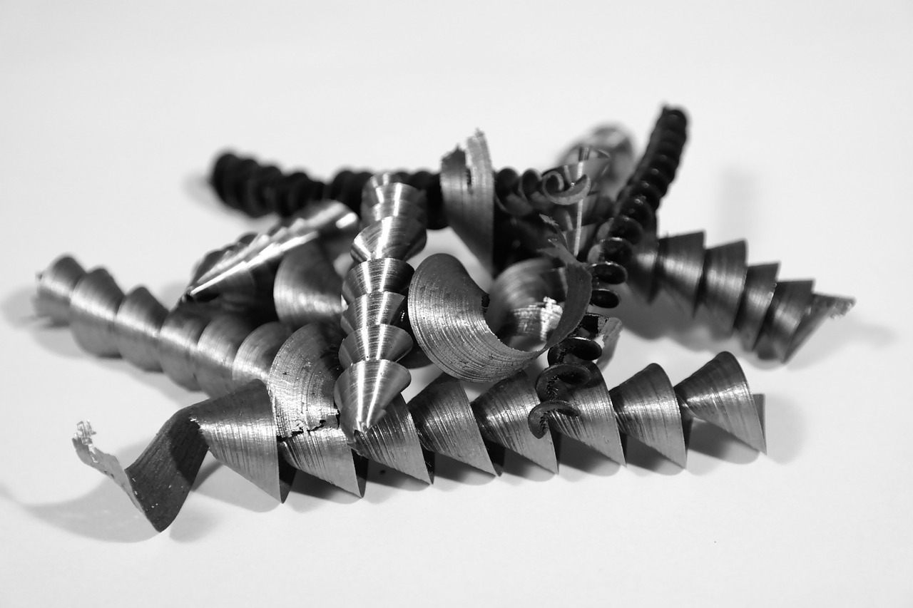
When machining metals with machines like lathes or milling machines, various shapes of cutting chips (helical, ribbon, or broken) are generated. These chips reveal a lot through their color, shape, length, etc.
In this article, we will primarily focus on the chips generated during lathe machining.
1.Why Are Chips Colored?
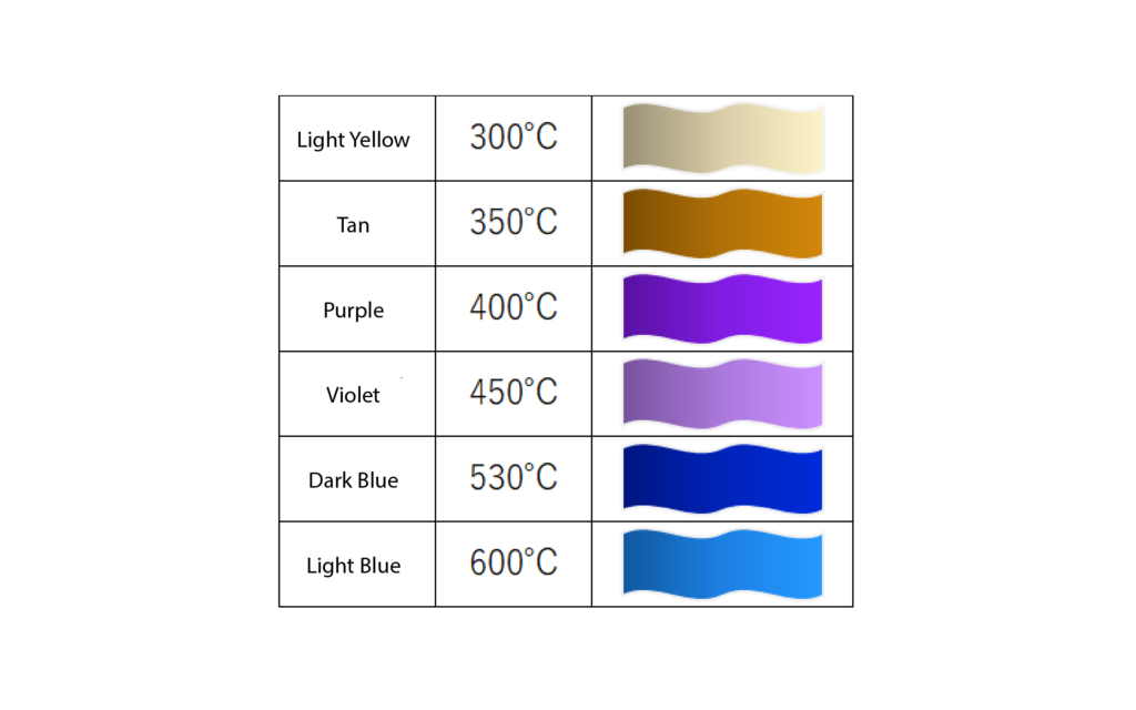
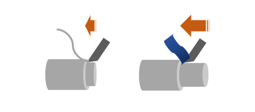
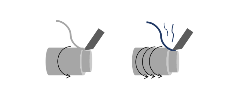
Chips can change color after machining, with some taking on a bluish hue or appearing iridescent, depending on the viewing angle. This phenomenon, called interference color (or temper color), is like what is observed on CDs, DVDs, or soap bubbles, and results from the reflection of light.
In lathe machining, the workpiece rotates while the tool is applied against it, generating significant heat due to pressure and friction. This creates a thin film called an oxide layer on the metal, which causes diffuse light reflection. The thickness of this film varies with temperature, producing different colors.
By observing the color of the chips, one can estimate the temperature generated during machining, which helps determine if the cutting conditions and tool were appropriate. Excessive temperature can reduce the tool’s lifespan, so it is crucial to maintain an adequate cutting temperature.
Interference colors are more common in dry machining (without cutting oil or coolant) and less common in wet machining (with cutting oil or coolant).
2.What the Chip Shape Reveals
During machining, the tool is applied against the workpiece, and the chip shape depends on the tool material, application angle, and cutting conditions (depth of cut, feed rate, spindle speed, etc.).
The chip shape indicates the material’s machinability and provides information on machining accuracy, including surface roughness and flatness, as well as cutting resistance and tool conditions.
Although classifying chip shapes can be complex, the JIS (Japanese Industrial Standards) divides them into four types:
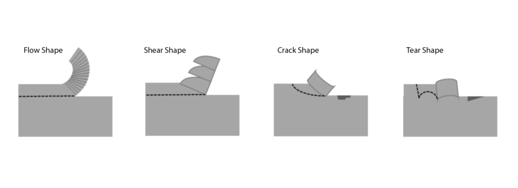
Flow Shape
When cutting conditions and tool conditions are good, and cutting resistance and variation are low and stable, flow-shaped chips are obtained. This indicates good machining accuracy.
Shear Shape
When variations occur during cutting, shear-shaped chips are obtained, indicating lower machining accuracy than flow-shaped chips. If there are slight problems with cutting conditions or cutting tools, or when machining slightly brittle materials, this shape may also appear.
Crack Shape
With very brittle materials, instead of forming flow-shaped chips, the material tends to crack before the chips can be removed, resulting in poor machining accuracy.
Tear Shape
When chips are not well evacuated, they interfere with cutting, forming tear-shaped chips. This phenomenon often leads to cracks on the cutting surface, which results in reduced machining accuracy. Tear-shaped chips can also be observed when machining ductile (viscous) materials.
Built-Up Edges That Cause Tear-Shaped Chips
Built-up edges form when chips adhere to the tool during cutting, becoming part of the tool. These chips attach and detach repeatedly, disrupting the cut and generating a torn surface. To avoid this, one can change the tool material, adjust the cutting angle, deliberately generate heat to prevent adhesion, or use cutting oil during machining.
3.What the Length and Number of Loops of the Chips Reveal
Chips can be very long (several meters) or short (a few millimeters to a few centimeters).
These lengths indicate different things:
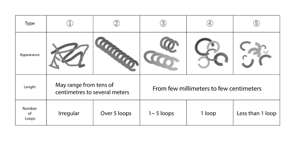
Types ① and ②, with long chips, can wrap around the workpiece or machine, risking scratches or halting operation. Although chip length depends on cutting conditions, ductile materials like aluminum, stainless steel, and copper alloys naturally produce long chips.
This issue can be addressed by using tools equipped with a chip breaker function, which intermittently cuts the chips, or by introducing machines equipped with an oscillation cutting system that creates minute vibrations to prevent the formation of long chips.
Types ③ and ④ are generally preferred as they indicate stable cutting conditions. Their moderate length reduces the risk of wrapping and facilitates evacuation, thus improving efficiency.
Type ⑤ indicates unstable cutting conditions, potentially due to inappropriate parameters or tools. The chips are scattered, and the surface finish is often rough.
4.Effects of Cutting Conditions on Chips and Machined Surface
Cutting parameters influence chip shape:
Increasing the depth of cut makes chips thicker, while too shallow a depth can cause the tool to slip on the surface (Slip phenomenon and scrape phenomenon). The higher the depth of cut, the greater the thermal load on the tool, and the rougher the machined surface becomes.

Increasing the feed rate increases chip width, speeding up the process but reducing surface quality and increasing the load on the tool increases the heat generated.
Increasing the spindle speed increases cutting speed, which can generate excessive heat if conditions are not suitable. Chips will be better quality in optimal conditions but unstable in inadequate conditions.
Note : Differences of Chip Shape by Machining Methods
Turning operation is broadly classified as rough and finishing machining.
As the names imply, rough machining involves cutting to achieve a rough shape, whereas finishing machining focuses on smoothing the surface and making fine adjustments in the final stages.
In rough machining, the depth of cut and feed rate are generally high, producing thick and wide chips. In finishing machining, the chips are thinner and narrower.
5.Relationship Between Tool Condition and Chips
Cutting tools undergo high temperatures and pressures. Harsh cutting conditions increase tool wear, cracks, and breakages. A heavily tool load produces poor-quality chips, indicating tool wear or inappropriate cutting parameters.
Different tools have various shapes and materials, each suited to specific cutting types and recommended cutting conditions. If chips are abnormal despite similar conditions to usual, it may indicate a worn tool, an unsuitable tool, a parameter error of cutting conditions, or an unsuitable material.
6.Summary
Chips thus reveal various crucial pieces of information:
- -The type of material being machined and if it is correct.
- -The appropriate choice of tool.
- -The adequate depth of cut, feed rate, and rotation speed.
- -Conformity to machining precision requirements.
- -The tool’s wear condition.
Each of these pieces of information is essential, underscoring the importance of regularly monitoring the state of the chips.